REVOLVED BOSS/BASE & REVOLVED CUT
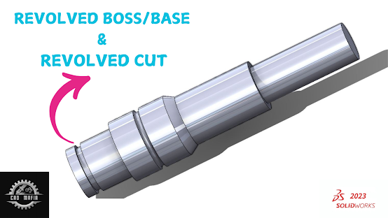
In SolidWorks, a "Revolved Boss" is a feature that allows you to create a 3D solid body by rotating a 2D sketch around an axis. This technique is commonly used for creating parts with rotational symmetry, like shafts, disks, or any part that can be defined by a profile that rotates around a central axis.
Here's how you can create a Revolved Boss in SolidWorks:
Steps to Create a Revolved Boss:
Start a New Part:
- Open SolidWorks and create a new part document by clicking on
File > Newand selecting "Part".
- Open SolidWorks and create a new part document by clicking on
Create a Sketch:
- Choose a plane to create the sketch (e.g., the Front Plane, Top Plane, or Right Plane).
- Click on the
Sketchtab, then selectSketchand draw the profile that will be revolved. For example, a half-profile of a cylinder or a shape you want to rotate. - Ensure your sketch has one end connected to the center of the axis of revolution. You can use a centerline to define the axis of rotation.
Select Revolved Boss/Base:
- Once your sketch is completed, exit the sketch by clicking
Exit Sketch. - Now, click on the
Featurestab, and selectRevolved Boss/Base. This option is used to turn your 2D profile into a 3D body by revolving it around an axis.
- Once your sketch is completed, exit the sketch by clicking
Define the Axis:
- The next step is to define the axis around which your sketch will be revolved. If you used a centerline in your sketch, SolidWorks will automatically recognize it as the axis.
- If you didn’t, you can select an existing edge or plane as the axis of revolution.
Set the Revolve Angle:
- Define the angle of revolution. You can specify a full 360° revolution, or any other angle depending on your design.
Complete the Feature:
- After setting the axis and angle, click
OKto create the revolved feature.
- After setting the axis and angle, click
Modify the Feature (Optional):
- If needed, you can adjust or edit the revolve feature later by right-clicking on the feature in the Feature Manager and selecting
Edit Feature.
- If needed, you can adjust or edit the revolve feature later by right-clicking on the feature in the Feature Manager and selecting
Example: Creating a Revolved Cylinder
- Draw a half-circle on the Right Plane.
- Set the center of the circle at the origin (which will be the axis of revolution).
- Use the
Revolved Boss/Basetool to revolve the sketch 360° around the centerline.
This process will generate a solid cylinder, as the half-circle profile will be revolved around the central axis.
REVOLVED CUTA Revolved Cut in SolidWorks is similar to the Revolved Boss/Base feature but instead of adding material to a part, it removes material by revolving a 2D sketch around an axis. This is often used to create features like holes, slots, or cavities that are rotational in nature, such as when you need to create a cut that follows the shape of the original sketch.
Steps to Create a Revolved Cut in SolidWorks:
Start a New Part:
- Open SolidWorks and create a new part by selecting
File > Newand then choosing "Part".
- Open SolidWorks and create a new part by selecting
Create a Sketch:
- Select a plane (e.g., Front Plane, Top Plane, or Right Plane) where you'll create the 2D sketch.
- Create the profile that you want to revolve and cut. This can be a line, circle, arc, or any other shape. The key is that your sketch should be on one side of the axis, and the sketch should not fully enclose the area you want to remove.
For example, if you want to create a hole through the center of a cylinder, you might draw a partial circle (an arc) on one side of the axis.
Define the Axis of Revolution:
- It's important to ensure that your sketch is properly aligned with the axis around which the revolution will occur. This axis is typically a centerline, but you can also use any edge or face as an axis for revolution.
- If you don’t have a centerline, you can create one as part of your sketch.
Select the Revolved Cut Feature:
- After finishing the sketch, exit the sketch by clicking on
Exit Sketch. - Next, click on the
Featurestab, and then chooseRevolved Cut. This feature will use the 2D sketch and revolve it around the axis to create a cut.
- After finishing the sketch, exit the sketch by clicking on
Define the Axis:
- You’ll be prompted to select the axis of revolution (if not automatically detected). This could be a centerline or any edge that you want to use for the revolution.
Set the Revolve Angle:
- Define the angle of revolution. Usually, this is 360° to create a full cut around the part, but you can specify a smaller angle if you want to make a partial cut.
Complete the Cut:
- Once the axis and angle are defined, click
OKto create the revolved cut. SolidWorks will remove material by revolving your sketch around the axis, cutting the part in the process.
- Once the axis and angle are defined, click
Example: Creating a Revolved Cut for a Hole
Create a Circle Sketch:
- Start by drawing a circle on the Right Plane, with its center at the origin. This circle will be the profile to cut through the part.
Create a Centerline:
- Draw a centerline from the origin to define the axis of revolution for the cut.
Draw a Partial Circle:
- Instead of a full circle, draw an arc or line that represents the portion of the profile you want to cut away. This could be a quarter circle or any segment.
Select Revolved Cut:
- Once your sketch is complete, exit the sketch, go to the
Featurestab, and selectRevolved Cut. - Select the centerline or any axis as the reference for revolution.
- Once your sketch is complete, exit the sketch, go to the
Complete the Cut:
- SolidWorks will cut through the part using the shape you created, revolving it around the centerline.
- SolidWorks will cut through the part using the shape you created, revolving it around the centerline.


No comments:
Post a Comment